HYDRODYNAMICS OF PUMPS
by Christopher Earls Brennen © Concepts NREC 1994
CHAPTER 2.
BASIC PRINCIPLES
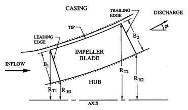
The geometry of a generalized turbomachine rotor is sketched in figure
2.1,
and consists of a set of rotor blades (number = ZR) attached to a hub and
operating within a static casing. The radii of the inlet blade tip, inlet
blade hub, discharge blade tip, and discharge blade hub are denoted by
RT1, RH1, RT2, and RH2, respectively. The discharge blade
passage is inclined to the axis of rotation at an angle,
 , which
would be close to 90° in the case of a
centrifugal pump, and much
smaller in the case of an axial flow machine.
In practice, many pumps and turbines
are of the ``mixed flow'' type
, in which the typical or mean discharge
flow is at some intermediate angle, 0<
 <90°.
<90°.
|
| Figure 2.1 Cross-sectional view through the axis of a pump impeller. |
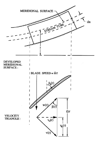
The flow through a general rotor is normally visualized by developing a meridional surface (figure 2.2), that can either correspond to an axisymmetric stream surface, or be some estimate thereof. On this meridional surface (see figure 2.2) the fluid velocity in a non-rotating coordinate system is denoted by v(r) (with subscripts 1 and 2 denoting particular values at inlet and discharge) and the corresponding velocity relative to the rotating blades is denoted by w(r). The velocities, v and w, have components vθ and wθ in the circumferential direction, and vm and wm in the meridional direction. Axial and radial components are denoted by the subscripts a and r. The velocity of the blades is Ω r. As shown in figure 2.2, the flow angle β(r) is defined as the angle between the relative velocity vector in the meridional plane and a plane perpendicular to the axis of rotation. The blade angle βb(r) is defined as the inclination of the tangent to the blade in the meridional plane and the plane perpendicular to the axis of rotation. If the flow is precisely parallel to the blades, β=βb. Specific values of the blade angle at the leading and trailing edges (1 and 2) and at the hub and tip (H and T) are denoted by the corresponding suffices, so that, for example, βbT2 is the blade angle at the discharge tip.
|
| Figure 2.2 Developed meridional surface and velocity triangle. |
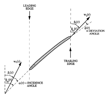
At the leading edge it is important to know the angle α(r) with which the flow meets the blades, and, as defined in figure 2.3,
 | ......(2.1) |
The incidence angle should not be confused with the ``angle of attack'', which is the angle between the incoming relative flow direction and the chord line (the line joining the leading edge to the trailing edge). Note, however, that, in an axial flow pump with straight helicoidal blades, the angle of attack is equal to the incidence angle.
|
| Figure 2.3 Repeat of figure 2.2 showing the definitions of the incidence angle at the leading edge and the deviation angle at the trailing edge. |
At the trailing edge, the difference between the flow angle and the blade angle is again important. To a first approximation one often assumes that the flow is parallel to the blades, so that β2(r)=βb2(r). A departure from this idealistic assumption is denoted by the deviation angle, δ(r), where, as shown in figure 2.3:
 | ......(2.2) |
|
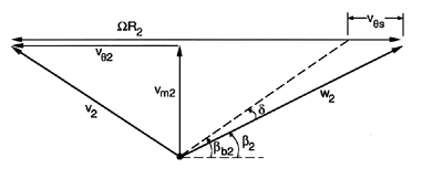
| Figure 2.4 Velocity vectors at discharge indicating the slip velocity, vθs. |
Deviation angles in radial machines are traditionally represented by the slip velocity, vθs, which is the difference between the actual and ideal circumferential velocities of the discharge flow, as shown in figure V1. It follows that
 | ......(2.3) |
 | ......(2.4) |
 | ......(2.5) |
2.2 CASCADES
|
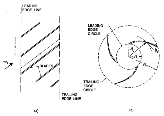
| Figure 2.5 Schematics of (a) a linear cascade and (b) a radial cascade. |
We now turn to some specific geometric features that occur frequently in discussions of pumps and other turbomachines. In a purely axial flow machine, the development of a cylindrical surface within the machine produces a linear cascade of the type shown in figure 2.5(a). The centerplane of the blades can be created using a ``generator'', say z=z*(r), which is a line in the rz-plane. If this line is rotated through a helical path, it describes a helicoidal surface of the form
 | ......(2.6) |
It is convenient to use the term ``simple'' cascade to refer to those geometries for which the blade angle, βb, is constant whether in an axial, radial, or mixed flow machine. Clearly, the flat plate cascade is the axial flow version of a simple cascade.
Now compare the geometries of the cascades at different radii within an axial flow machine. Later, we analyse the cavitating flow occurring at different radii (see figure 7.35). Often the pitch at a given axial position is the same at all radii. Then it follows that the radial variation in the blade angle, βb(r), must be given by
 | ......(2.7) |
In a centrifugal machine in which the flow is purely radial, a cross-section of the flow would be as shown in figure 2.5(b), an array known as a "radial cascade". In a simple radial cascade, the angle, βb, is uniform along the length of the blades. The resulting blade geometry is known as a logarithmic spiral, since it follows that the coordinates of the blades are given by the equation
 | ......(2.8) |
In any of type of pump, the ratio of the length of a blade passage to its width is important in determining the degree to which the flow is guided by the blades. The solidity, s, is the geometric parameter that is used as a measure of this geometric characteristic, and s can be defined for any simple cascade as follows. If we identify the difference between the θ coordinates for the same point on adjacent blades (call this ΔθA) and the difference between the θ coordinates for the leading and trailing edges of a blade (call this ΔθB), then the solidity for a simple cascade is defined by
 | ......(2.9) |
 | ......(2.10) |
 | ......(2.11) |
In practice, there exist many ``mixed flow'' pumps whose geometries lie
between that of an axial flow machine ( =0, figure 2.1) and
that of a radial machine (
 =π/2). The most general analysis of
such a pump would require a cascade geometry in which figures 2.5(a)
and 2.5(b) were projections of the geometry of a
meridional surface (figure 2.2) onto a cylindrical surface and onto a
plane perpendicular to the axis, respectively. (Note that the βb
marked in figure 2.5(b) is not appropriate when that diagram is used
as a projection). We shall not attempt such
generality here; rather, we observe that the meridional surface in many
machines is close to conical. Denoting the inclination of the cone to the
axis by
  , we can use equation 2.9 to obtain an expression
for the solidity of a simple cascade in this conical geometry,
 | ......(2.12) |
2.3 FLOW NOTATION
The flow variables that are important are, of course, the static pressure, p, the total pressure, pT, and the volume flow rate, Q. Often the total pressure is defined by the total head, pT/ρ g. Moreover, in most situations of interest in the context of turbomachinery, the potential energy associated with the earth's gravitational field is negligible relative to the kinetic energy of the flow, so that, by definition
 | ......(2.13) |
 | ......(2.14) |
 | ......(2.15) |
It follows that, in a pump with an incompressible fluid, the overall characteristics that are important are the volume flow rate, Q, and the total pressure rise, ρ gH, where H = (pT2-pT1)/ρ g is the total head rise. These dimensional characteristics are conveniently nondimensionalized by defining a head coefficient, ψ,
 | ......(2.16) |
 | ......(2.17) |
 | ......(2.18) |
Frequently, the conditions at inlet and/or discharge are nonuniform and one must subdivide the flow into annular streamtubes, as indicated in figure 2.2. Each streamtube must then be analysed separately, using the blade geometry pertinent at that radius. The mass flow rate, m, through an individual streamtube is given by
 | ......(2.19) |
Conservation of mass requires that m have the same value at inlet and discharge. This yields a relation between the inlet and discharge meridional velocities, that involves the cross-sectional areas of the streamtube at these two locations. The total volume flow rate through the turbomachine, Q, is then related to the velocity distribution at any location by the integral
 | ......(2.20) |
The total head rise across the machine, H, is given by the integral of the total rate of work done on the flow divided by the total mass flow rate:
 | ......(2.21) |
2.4 SPECIFIC SPEED
At the beginning of any pump design process, neither the size nor the shape of the machine is known. The task the pump is required to perform is to use a shaft rotating at a frequency, Ω (in rad/s), to pump a certain flow rate, Q (in m3/s) through a head rise, H (in m). As in all fluid mechanical formulations, one should first seek a nondimensional parameter (or parameters) which distinguishes the nature of this task. In this case, there is one and only one nondimensional parametric group that is appropriate and this is known as the ``specific speed'', denoted by N. The form of the specific speed is readily determined by dimensional analysis:
 | ......(2.22) |
The above definition of the specific speed has employed a consistent set of units, so that N is truly dimensionless. With these consistent units, the values of N for most common turbomachines lie in the range between 0.1 and 4.0 (see below). Unfortunately, it has been traditional in industry to use an inconsistent set of units in calculating N. In the USA, the g is dropped from the denominator, and values for the speed, flow rate, and head in rpm, gpm, and ft are used in calculating N. This yields values that are a factor of 2734.6 larger than the values of N obtained using consistent units. The situation is even more confused since the Europeans use another set of inconsistent units (rpm, m3/s, head in m, and no g) while the British employ a definition similar to the U.S., but with Imperial gallons rather than U.S. gallons. One can only hope that the pump (and turbine) industries would cease the use of these inconsistent measures that would be regarded with derision by any engineer outside of the industry. In this monograph, we shall use the dimensionally consistent and, therefore, universal definition of N.
Note that, since Q and gH were separately nondimensionalized in the definitions 2.16 and 2.17, N can be related to the corresponding flow and head coefficients by
 | ......(2.23) |
 =π/2),
the quantity within the square brackets reduces to 2π B2/RT2.
Since turbomachines are designed for specific tasks, the subscripted ND will be used to denote the design value of the specific speed for a given machine.
2.5 PUMP GEOMETRIES
|
|
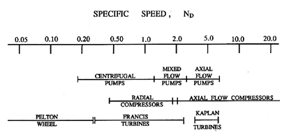
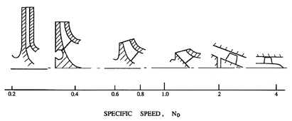
| Figure 2.6 Ranges of specific speeds for typical turbomachines and typical pump geometries for different design speeds (from Sabersky, Acosta and Hauptmann 1989). |
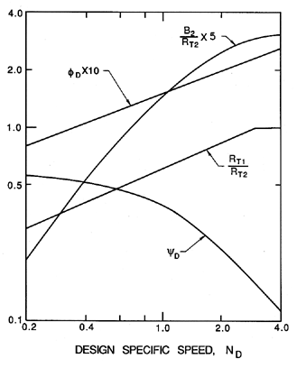
Since the task specifications for a pump (or turbine or compressor or other machine) can be reduced to the single parameter, ND, it is not surprising that the overall or global geometries of pumps, that have evolved over many decades, can be seen to fit quite neatly into a single parameter family of shapes. This family is depicted in figure 2.6. These geometries reflect the fact that an axial flow machine, whether a pump, turbine, or compressor, is more efficient at high specific speeds (high flow rate, low head) while a radial machine, that uses the centrifugal effect, is more efficient at low specific speeds (low flow rate, high head). The same basic family of geometries is presented quantitatively in figure 2.7, where the anticipated head and flow coefficients are also plotted. While the existence of this parametric family of designs has emerged almost exclusively as a result of trial and error, some useful perspectives can be obtained from an approximate analysis of the effects of the pump geometry on the hydraulic performance (see section 4.3).
|
| Figure 2.7 General design guidelines for pumps indicating the optimum ratio of inlet to discharge tip radius, RT1/RT2, and discharge width ratio, B2/RT2, for various design specific speeds, ND. Also shown are approximate pump performance parameters, the design flow coefficient, φD, and the design head coefficient, ψD (adapted from Sabersky, Acosta and Hauptmann 1989). |
|
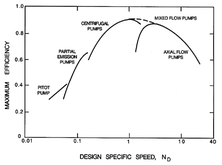
| Figure 2.8 Compilation by Balje (1981) of maximum efficiencies for various kinds of pumps as a function of design specific speed, ND. Since efficiency is also a function of Reynolds number the data has been corrected to a Reynolds number, 2Ω R2T2/ν, of 108. |
|
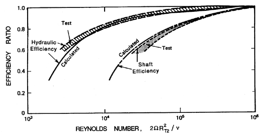
| Figure 2.9 The dependence of hydraulic efficiency, ηp, and shaft efficiency, ηS, on Reynolds number, 2Ω R2T2/ν (from Balje 1981). |
Normally, turbomachines are designed to have their maximum efficiency at the design specific speed, ND. Thus, in any graph of efficiency against specific speed, each pump geometry will trace out a curve with a maximum at its optimum specific speed, as illustrated by the individual curves in figure 2.8. Furthermore, Balje (1981) has made note of another interesting feature of this family of curves in the graph of efficiency against specific speed. First, he corrects the curves for the different viscous effects which can occur in machines of different size and speed, by comparing the data on efficiency at the same effective Reynolds number using the diagram reproduced as figure 2.9. Then, as can be seen in figure 2.8, the family of curves for the efficiency of different types of machines has an upper envelope with a maximum at a specific speed of unity. Maximum possible efficiencies decline for values of ND greater or less than unity. Thus the ``ideal'' pump would seem to be that with a design specific speed of unity, and the maximum obtainable efficiency seems to be greatest at this specific speed. Fortunately, from a design point of view, one of the specifications has some flexibility, namely the shaft speed, Ω. Though the desired flow rate and head rise are usually fixed, it may be possible to choose the drive motor to turn at a speed, Ω, which brings the design specific speed close to the optimum value of unity.
2.6 ENERGY BALANCE
The next step in the assessment of the performance of a turbomachine is to consider the application of the first and second laws of thermodynamics to such devices. In doing so we shall characterize the inlet and discharge flows by their pressure, velocity, enthalpy, etc., assuming that these are uniform flows. It is understood that when the inlet and discharge flows are non-uniform, the analysis actually applies to a single streamtube and the complete energy balance requires integration over all of the streamtubes.
The basic thermodynamic measure of the energy stored in a unit mass of flowing fluid is the total specific enthalpy (total enthalpy per unit mass) denoted by hT and defined by
 | ......(2.24) |
Consider the steady state operation of a fluid machine
in which the entering fluid has a total specific enthalpy of
hT1, the discharging fluid has a total specific enthalpy of
hT2, the mass flow rate is m, the net rate of heat addition to the
machine is  , and the net rate
of work done on the fluid in the
machine by external means is
  .
It follows from the first law of thermodynamics that
 | ......(2.25) |
Now consider incompressible, inviscid flow. It is a fundamental property of such a flow that it contains no mechanism for an exchange of thermal and mechanical energy, and, therefore, equation 2.25 divides into two parts, governing the mechanical and thermal components of the total enthalpy, as follows
 | ......(2.26) |
 | ......(2.27) |
It follows that, if T is the torque applied by the impeller to the fluid,
then the rate of work done on the fluid is
 =T Ω.
Consequently, in the case of an ideal fluid which is incompressible and
inviscid, equation 2.26 yields a relation connecting the total
pressure rise across the pump, pT2 - pT1, the mass flow rate, m, and the
torque:
 | ......(2.28) |
Furthermore, the second law of thermodynamics implies that, in the presence of irreversible effects such as those caused by viscosity, the equality in equation 2.28 should be replaced by an inequality, namely a ``less than'' sign. Consequently, in a real pump operating with an incompressible fluid, viscous effects will cause some of the input energy to be converted to heat rather than to an increase in the stored energy in the fluid. It follows that the right hand side of equation 2.28 is the actual work done on the fluid by the impeller, and the left hand side is the fraction of that work which ends up as mechanical energy stored in the fluid. It is, therefore, appropriate to define a quantity, ηP, known as the pump hydraulic efficiency, to represent that fraction of the work done on the fluid that ends up as an increase in the mechanical energy stored in the fluid:
 | ......(2.29) |
Of course, additional mechanical losses may occur in a pump. These can cause the rate of work transmitted through the external shaft of the pump to be greater than the rate at which the impeller does work on the fluid. For example, losses may occur in the bearings or as a result of the ``disk friction'' losses caused by the fluid dynamic drag on other, non-active surfaces rotating with the shaft. Consequently, the overall (or shaft) efficiency, ηS, may be significantly smaller than ηP. For approximate evaluations of these additional losses, the reader is referred to the work of Balje (1981).
Despite all these loss mechanisms, pumps can be surprisingly efficient. A well designed centrifugal pump should have an overall efficiency in the neighborhood of 85% and some very large pumps (for example those in the Grand Coulee Dam) can exceed 90%. Even centrifugal pumps with quite simple and crude geometries can often be 60% efficient.
2.7 IDEALIZED NONCAVITATING PUMP PERFORMANCE
It is useful at this point to develop an approximate and idealized evaluation of the hydraulic performance of a pump in the absence of cavitation. This will take the form of an analytical expression for the head rise (or ψ) as a function of the flow rate (or φ2).
To simplify this analysis it is assumed that the flow is incompressible, axisymmetric and steady in the rotating framework of the impeller blades; that the blades are infinitely thin; and that viscous losses can be neglected. Under these conditions the flow in any streamtube, such as depicted in figure 2.2, will follow the Bernoulli equation for a rotating system (see, for example, Sabersky, Acosta and Hauptmann 1989),
 | ......(2.30) |
Using the definition of the total pressure (equation 2.13) and the relations between the velocities derived from the velocity triangles of figure 2.2, equation 2.30 can be manipulated to yield the following expression for the total pressure rise, (pT2-pT1), for a given streamtube:
 |
|
 | ......(2.33) |
It is important to note that the above results can be connected with those of the preceding section by applying the angular momentum theorem (Newton's second law of motion applied to rotational motion) to relate the torque, T, to the net flux of angular momentum out of the pump:
 | ......(2.34) |
2.8 SEVERAL SPECIFIC IMPELLERS AND PUMPS
|
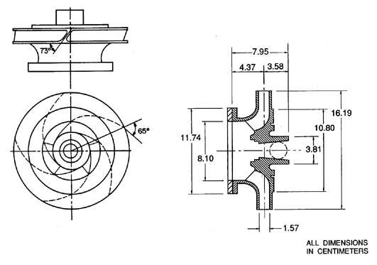
| Figure 2.10 A centrifugal pump impeller designated Impeller X. |
|
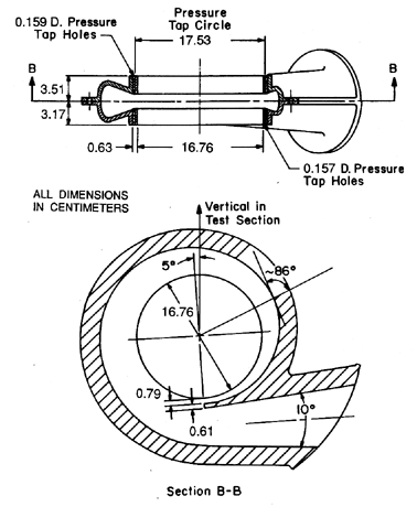
| Figure 2.11 A vaneless spiral volute (designated Volute A) designed to be matched to Impeller X. |
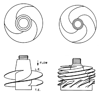
|
| Figure 2.12 Two cavitating inducers for which performance data is presented. On the left a 7.58cm diameter, 9° helical Impeller V (a 10.2cm version is designated Impeller VII). On the right a 7.58cm diameter scale model of the impeller in the SSME low pressure LOX turbopump, Impeller IV (a 10.2cm version is designated Impeller VI). |
Throughout this monograph, we shall make reference to experimental data on various phenomena obtained with several specific impellers and pumps. It is appropriate at this point to include a brief description of these components. The descriptions will also serve as convenient examples of pump geometries.
Impeller X, which is shown in figure 2.10, is a five-bladed centrifugal pump impeller made by Byron Jackson Pump Division of Borg Warner International Products. It has a discharge radius, RT2=8.1cm, a discharge blade angle, βbT2, of 23°, and a design specific speed, ND, of 0.57. Impeller X was often tested in combination with Volute A (figure 2.11), a single exit, spiral volute with a base circle of 18.3cm and a spiral angle of 4°. It is designed to match Impeller X at a flow coefficient of φ2=0.092. This implies that the principles of fluid continuity and momentum have been utilized in the design, so that the volute collects a circumferentially uniform discharge from the impeller and channels it to the discharge line in such a way that the pressure in the volute is circumferentially uniform, and in a way that minimizes the viscous losses in the decelerating flow. For given volute and impeller geometries, these objectives can only by met at one ``design'' flow coefficient, as described in section 4.4. We would therefore expect that the hydraulic losses would increase, and the efficiency decrease, at off-design conditions. It is valuable to emphasize that the performance of a pump depends not only on the separate designs of the impeller and volute but also on the matching of the two components.
Two particular axial flow pumps or inducers, designed to function with cavitation, will also be referred to frequently. These are shown in figure 2.12. In a number of contexts, data for several simple 9° helical inducers (βbT1=9° ) will be used for illustrative purposes, and a typical geometry is shown on the left of figure 2.12. Two 7.58cm diameter versions were deployed: Impeller III had straight, radial leading edges and Impeller V, with swept leading edges, is shown in figure 2.12. A 10.2cm diameter version with swept leading edges is designated Impeller VII.
The second inducer geometry is pertinent to a somewhat lower specific speed. Impellers IV (7.58cm diameter) and VI (10.2cm diameter) were scale models of the low pressure liquid oxygen impeller in the Space Shuttle Main Engine (SSME). These have a design flow coefficient of about 0.076; other dimensions are given in table 7.1. Furthermore, some detailed data on blade angles, βb1(r), and blade thickness are given in figure 7.39.
- Balje, O.E. (1981). Turbomachines. A guide to design, selection and theory. John Wiley and Sons, New York.
- Sabersky, R.H., Acosta, A.J. and Hauptmann, E.G. (1989). Fluid flow (3rd edition), Chapters 12 and 13. Macmillan Publ. Co.
- Stodola, A. (1927). Steam and gas turbines. Volumes I and II. McGraw-Hill, New York.
Last updated 12/1/00.
Christopher E. Brennen