HYDRODYNAMICS OF PUMPS
by Christopher Earls Brennen © Concepts NREC 1994
CHAPTER 10.
RADIAL AND ROTORDYNAMIC FORCES
10.1 INTRODUCTION
This chapter is devoted to a discussion of the various fluid-induced radial and rotordynamic forces which can occur in pumps and other turbomachines. It has become increasingly recognized that the reliability and acceptability of modern turbomachines depend heavily on the degree of vibration and noise which those machines produce (Makay and Szamody 1978), and that one of the most common sources of vibration is associated with the dynamics of the shaft and its related components, bearings, seals, and impellers (Duncan 1966-67, Doyle 1980, Ehrich and Childs 1984). It is clear that the modern pump designer (see, for example, Ek 1978, France 1986), or turbine designer (see, for example, Pollman et al. 1978), must pay particular attention to the rotordynamics of the shaft to ensure not only that the critical speeds occur at expected rotational rates, but also that the vibration levels are minimized. It is, however, important to note that not all shaft vibrations are caused by rotordynamic instability. For example, Rosenmann (1965) reports oscillating radial forces on cavitating inducers that are about 20% of the axial thrust, and are caused by flow oscillations, not rotordynamic oscillations. Also, Marscher (1988) investigated shaft motions induced by the unsteady flows at inlet to a centrifugal impeller operating below the design flow rate.
Texts such as Vance (1988) provide background on the methods of rotordynamic analysis. We focus here only on some of the inputs which are needed for that analysis, namely the forces caused by fluid motion in the bearing, seal, or impeller. One reason for this emphasis is that these inputs represent, at present, the area of greatest uncertainty insofar as the rotordynamic analysis is concerned.
We shall attempt to present data from many different sources using a common notation and a common nondimensionalizing procedure. This background is reviewed in the next section. Subsequently, we shall examine the known fluid-induced rotordynamic effects in hydrodynamic bearings, seals, and other devices. Then the forces acting on an impeller, both steady radial and rotordynamic forces, will be reviewed both for centrifugal pumps and for axial flow inducers.
10.2 NOTATION
|
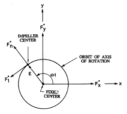
| Figure 10.1 Schematic showing the relationship between the forces in the pump frame, F*x, F*y, the rotordynamic forces, F*n, F*t, the impeller center, the whirl orbit, and the volute geometry. |
The forces that the fluid imparts to the rotor in a plane perpendicular to the axis of rotation are depicted in figure 10.1, and are decomposed into components in the directions x and y, where this coordinate system is fixed in the framework of the pump. The instantaneous forces are denoted by F*x(t), F*y(t), and the time-averaged values of these forces in the stationary frame are denoted by F*0x, F*0y. By definition, these are the steady forces commonly referred to as the radial forces or radial thrust. Sometimes it is important to know the axial position of the line of action of these forces. Alternatively, one can regard the x,y axes as fixed at some convenient axial location. Then, in addition to the forces, F*x(t) and F*y(t), the fluid-induced bending moments, M*x(t) and M*y(t), would be required information. The time-averaged moments will be defined by M*0x and M*0y.
Even if the location of the center of rotation were stationary at the origin of the xy plane (figure 10.1) the forces F*x(t), F*y(t) and moments M*x(t), M*y(t) could still have significant unsteady components. For example, rotor-stator interaction could lead to significant forces on the impeller at the blade passing frequencies. Similarly, there could be blade passing frequency components in the torque, T(t), and the axial thrust, as discussed earlier in section 8.2. For simplicity, however, they will not be included in the present mathematical formulation.
The other set of forces with which this chapter will be concerned are the fluid-induced rotordynamic forces that are caused by the displacement and motion of the axis of rotation. It will be assumed that this displacement is sufficiently small so that a linear perturbation model is accurate. Then
 | ......(10.1) |
 | ......(10.2) |
 | ......(10.3) |
 | ......(10.4) |
One particular feature of the rotordynamic matrices, [A] and [B], deserves special note. There are many geometries in which the rotordynamic forces should be invariant to a rotation of the x,y axes. Such will be the case only if
 | ......(10.5) |
 | ......(10.6) |
The prototypical displacement will clearly consist of a circular whirl motion of ``eccentricity'', ε, and whirl frequency, ω, so that x(t)=ε cosω t and y(t)=ε sinω t. As indicated in figure 10.1, an alternative notation is to define ``rotordynamic forces'', F*n and F*t, that are normal and tangential to the circular whirl orbit at the instantaneous position of the center of rotation. Note that F*n is defined as positive outward and F*t as positive in the direction of rotation, Ω. It follows that
 | ......(10.7) |
 | ......(10.8) |
 | ......(10.9) |
 | ......(10.10) |
Furthermore, it is conventional among rotordynamicists to decompose the matrix [A] into added mass, damping and stiffness matrices according to
 | ......(10.11) |
 | ......(10.12) |
 | ......(10.13) |
 | ......(10.14) |
Since m is often small and is frequently assumed to be negligible, the sign of the tangential force is approximately determined by the quantity kΩ/ωC. Thus rotordynamicists often seek to examine the quantity k/C=k*/ΩC*, which is often called the ``whirl ratio'' (not to be confused with the whirl frequency ratio, ω/Ω). Clearly larger values of this whirl ratio imply a larger range of frequencies for which the tangential force is destabilizing and a greater chance of rotordynamic instability.
In the last few paragraphs we have focused on the forces, but it is clear that a parallel construct is relevant to the rotordynamic moments. It should be recognized that each of the components of a turbomachine will manifest its own rotordynamic coefficients which will all need to be included in order to effect a complete rotordynamic analysis of the machine. The methods used in such rotordynamic analyses are beyond the scope of this book. However, we shall attempt to review the origin of these forces in the bearings, seals, and other components of the turbomachine. Moreover, both the main flow and leakage flows associated with the impeller will generate contributions. In order to permit ease of comparison between the rotordynamic effects contributed by the various components, we shall use a similar nondimensionalization for all the components.
10.3 HYDRODYNAMIC BEARINGS AND SEALS
Hydrodynamic bearings, seals, and squeeze-film dampers constitute a class of devices that involve the flow in an annulus between two cylinders; the inner cylinder is generally the shaft (radius, R) which is rotating at a frequency, Ω, and may also be whirling with an amplitude or eccentricity, ε, and a frequency, ω. The outer cylinder is generally static and fixed to the support structure. The mean clearance (width of the annulus) will be denoted by δ, and the axial length by L. In both hydrodynamic bearings and seals, the basic fluid motion is caused by the rotation of the shaft. In a seal, there is an additional axial flow due to the imposed axial pressure difference. In a squeeze-film damper, there is no rotational motion, but forces are generated by the whirl motion of the ``rotor''.
The Reynolds number is an important parameter in these flows, and it is useful to evaluate three different Reynolds numbers based on the rotational velocity, on the mean axial velocity, V (given by V=Q/ 2π Rδ where Q is the volumetric axial flow rate), and on the velocity associated with the whirl motion. These are termed the rotational, axial and whirl Reynolds numbers and are defined, respectively, by
 | ......(10.15) |
|
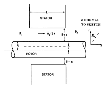
| Figure 10.2 Schematic of a short seal demonstrating the Lomakin effect. |
This is called the ``Bernoulli effect'' or ``inertia effect'', and can be simply explained as follows. When an eccentricity is introduced, the fluid velocities will be increased over that part of the rotor circumference where the clearance has been reduced. At Reynolds numbers much larger than unity, the Bernoulli equation is applicable, and higher velocities imply lower pressure. Therefore the pressure in the fluid is decreased where the clearance is small and, consequently, there will be a net force on the rotor in the direction of the displacement. This ``negative stiffness'' (K < 0) is important in the rotordynamics of seals and impellers.
Another parameter of importance is the ratio of the axial length to
radius, L/R, of the bearing or seal. For large L/R, the predominant
fluid motions caused by the rotordynamic perturbations occur in the
circumferential direction.
On the other hand, in a short seal or
bearing,
the predominant effect of the rotordynamic perturbation is to cause
circumferential variation in the axial fluid velocity. This gives rise to
the so-called ``Lomakin effect''
in short seals operating at high Reynolds numbers (Lomakin 1958).
The circumstances are sketched in figure 10.2, in which we use a
cylindrical coordinate system, (r,θ,z), to depict a plain annular
seal with a clearance, δ. The fluid velocity,
uz, is caused by the
pressure difference, Δ p=(p1-p2). We denote the axial velocity
averaged over the clearance by
 ,
and this will be a function of
θ when the rotor is displaced by an eccentricity, ε. The
Lomakin effect is caused by circumferential variations in
the entrance losses in this flow. On the side
with the smaller clearance, the entrance losses are smaller because
 is smaller.
Consequently, the mean pressure is larger on the side with the smaller
clearance, and the result is a restoring force due to this circumferential
pressure distribution. This is known as the
Lomakin effect, and
gives rise to a positive fluid-induced stiffness, K. Note that the
competing Bernoulli and Lomakin effects can cause the sign of the
fluid-induced stiffness of a seal to change as the geometry changes.
In the following sections we examine more closely some of the fluid-induced rotordynamic effects in bearings, seals, and impellers.
10.4 BEARINGS AT LOW REYNOLDS NUMBERS
|
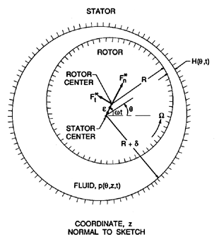
| Figure 10.3 Schematic of fluid-filled annulus between a stator and a rotating and whirling rotor. |
The rotordynamics of a simple hydrodynamic bearing operating at low Reynolds number (ReΩ « 1) will be examined first. The conventional approach to this problem (Pinkus and Sternlicht 1961) is to use Reynolds' approximate equation for the fluid motions in a thin film. In the present context, in which the fluid is contained between two circular cylinders (figure 10.3) this equation becomes
 | ......(10.16) |
The rotordynamic forces, F*n and F*t, then follow from
 | ......(10.17) |
Two simple asymptotic solutions are readily forthcoming for linear perturbations in which ε « δ. The first is termed the ``long bearing'' solution, and assumes, as discussed in the last section, that the dominant perturbations to the velocity occur in the circumferential velocities rather than the axial velocities. It follows that the second term in equation 10.16 can be neglected as small relative to the first term. Neglecting, in addition, all terms quadratic or higher order in ε, integration of equation 10.16 leads to
 | ......(10.18) |
 | ......(10.19) |
 | ......(10.20) |
The second, or ``short bearing'', solution assumes that the dominant perturbations to the velocities occur in the axial velocities; this usually requires L/R to be less than about 0.5. Then, assuming that the pressure is measured relative to a uniform and common pressure at both ends, z=0 and z=L, integration of equation 10.16 leads to
 | ......(10.21) |
 | ......(10.22) |
 | ......(10.23) |
It is particularly important to note that the tangential forces in both the long and short bearing solutions are negative for Ω < 2ω, and become positive for Ω > 2ω. This explains the phenomenon of ``oil whip'' in hydrodynamic bearings, first described by Newkirk and Taylor (1925). They reported that violent shaft motions occurred when the shaft speed reached a value twice the critical speed of the shaft. This phenomenon is the response of a dynamic system at its natural frequency when the exciting tangential force becomes positive, namely when Ω > 2ω (see Hori 1959). It is of interest to note that a similar critical condition occurs for high Reynolds number flow in the film (see equations 10.36 and 10.37).
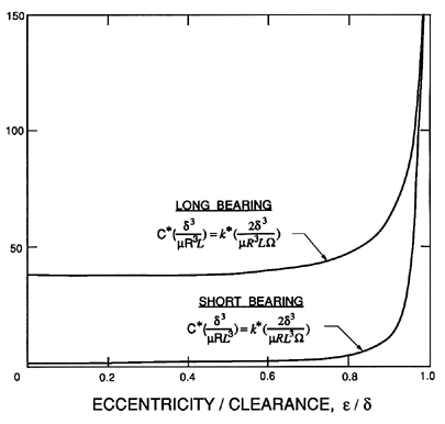
The simple linear results described above can be augmented in several ways. First, similar solutions can be generated for the more general case in which the eccentricity is not necessarily small compared with the clearance. The results (Vance 1988) for the long bearing become
 | ......(10.24) |
 | ......(10.25) |
 | ......(10.26) |
 | ......(10.27) |
|
| Figure 10.4 Dimensionless damping and cross-coupled stiffness for noncavitating long and short bearings as functions of the eccentricity ratio, ε/δ. |
Second, it is important to note that cavitation or gas dissolution in liquid-filled bearings can often result in a substantial fraction of the annulus being filled by a gas bubble or bubbles. The reader is referred to Dowson and Taylor (1979) for a review of this complicated subject. Quite crude approximations are often introduced into lubrication analyses in order to try to account for this ``cavitation''. The most common approximation is to assume that the two quadrants in which the pressure falls below the mean are completely filled with gas (or vapor) rather than liquid. Called a π-film cavitated bearing, this heuristic assumption leads to the following rotordynamic forces (Vance 1988). For the cavitated (π-film) long bearing
 | ......(10.28) |
 | ......(10.29) |
 | ......(10.30) |
 | ......(10.31) |
Finally, we note that all of the fluid inertial effects have been neglected in the above analyses, and, consequently, the question arises as to how the results might change when the Reynolds number, ReΩ, is no longer negligibly small. Such analyses require a return to the full Navier-Stokes equations, and the author has explored the solutions of these equations in the case of long bearings (Brennen 1976). In the case of whirl with constant eccentricity (dε/dt=0), it was shown that there are two separate sets of asymptotic results for Reω « δ3/R3, and for δ3/R3 « Reω « δ2/R2. For Reω « δ3/R3, the rotordynamic forces are
 | ......(10.32) |
 | ......(10.33) |
 | ......(10.34) |
 | ......(10.35) |
10.5 ANNULUS AT HIGH REYNOLDS NUMBERS
Consider now the flows of the last section when the Reynolds numbers become much greater than unity. The name ``bearing'' must be omitted, since the flow no longer has the necessary rotordynamic characteristics to act as a hydrodynamic bearing. Nevertheless, such flows are of interest since there are many instances in which rotors are surrounded by fluid annuli. Fritz (1970) used an extension of a lubrication theory in which he included fluid inertia and fluid frictional effects for several types of flow in the annulus, including Taylor vortex flow and fully turbulent flow. Though some of his arguments are heuristic, the results are included here because of their practical value. The rotordynamic forces which he obtains are
 | ......(10.36) |
 | ......(10.37) |
 | ......(10.38) |
The other terms in equations 10.36 and 10.37 that do not involve f are caused by the fluid inertia and are governed by the added mass, M*=πρ R3L/δ, which Fritz confirms by experimental measurements. Note that equations 10.36 and 10.37 imply rotordynamic coefficients as follows
 | ......(10.39) |
 | ......(10.40) |
10.6 SQUEEZE FILM DAMPERS
A squeeze film damper consists of a nonrotating cylinder surrounded by a fluid annulus contained by an outer cylinder. A shaft runs within the inner, nonrotating cylinder so that the latter may perform whirl motions without rotation. The fluid annulus is intended to damp any rotordynamic motions of the shaft. It follows that figure 10.3 can also represent a squeeze film damper as long as Ω is set to zero. The device is intended to operate at low Reynolds numbers, Reω, and several of the results already described can be readily adopted for use in a squeeze-film damper. Clearly analyses can be generated for both long and short squeeze film dampers. The long squeeze film damper is one flow for which approximate solutions to the full Navier-Stokes equations can be found (Brennen 1976). Two sets of asymptotic results emerge, depending on whether Reω is much less than, or much greater than, 72R/δ. In the case of thin films (δ « R), the rotordynamic forces for Reω « 72R/δ are
 | ......(10.41) |
 | ......(10.42) |
 | ......(10.43) |
 | ......(10.44) |
The relations 10.41 to 10.44 are limited to small amplitudes, ε « δ, and to values of ωε2/ν « 1. At larger amplitudes and Reynolds numbers, ωε2/ν, it is necessary to resort to lubrication analyses supplemented, where necessary, with inertial terms in the same manner as described in the last section. Vance (1988) delineates such an approach to squeeze film dampers.
|
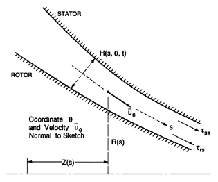
| Figure 10.5 Sketch of fluid filled annulus between a rotor and a stator for turbulent lubrication analysis. |
In an annular seal, the flows are usually turbulent because of the high
Reynolds numbers at which they operate. In this section we describe
the approaches taken to identify the rotordynamic properties of
these flows. Black and his co-workers (Black 1969, Black and Jensen
1970) were the first to attempt to identify and model the rotordynamics
of turbulent annular seals. Bulk flow models
(similar to those of Reynolds lubrication equations) were used. These
employ velocity components,
 and
and
 ,
that are averaged over the clearance.
Black and Jensen used several heuristic assumptions in their model,
such as the assumption that
 =RΩ/2. Moreover,
their governing equations do not reduce to recognizable
turbulent lubrication equations. These issues caused Childs (1983b)
to publish a
revised version of the bulk flow model and we will focus on
Childs' model here. Childs (1987, 1989) has also employed a
geometric generalization of the same bulk flow model to examine the
rotordynamic characteristics of
discharge-to-suction leakage flows around
shrouded centrifugal pump impellers, and it is therefore convenient to
include here the more general form of his analysis. The geometry
is sketched in figure 10.5, and is described by coordinates of the
meridian of the gap as given by
Z(s) and R(s), 0 < s < L, where the coordinate,
s, is measured along that meridian. The clearance is denoted by
H(s,θ,t) where the unperturbed value of H is δ(s).
The equations
governing the bulk flow are averaged over the clearance. This leads to
a continuity equation of the form
 | ......(10.45) |
 and
and
 are velocities averaged
over the local clearance. The meridional and circumferential momentum
equations are
 | ......(10.46) |
 | ......(10.47) |
 | ......(10.48) |
 | ......(10.49) |
 | ......(10.50) |
 | ......(10.51) |
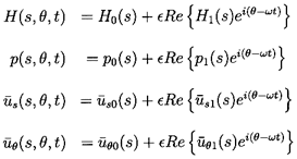 | ......(10.52) |
 , and
, and
 ),
and a second set of equations for the perturbation quantities
(p1,
 , and
, and
 );
terms which are of quadratic or higher order in
ε are neglected.
With the kind of complex geometry associated, say, with discharge-to-suction leakage flows in centrifugal pumps, it is necessary to solve both sets of equations numerically in order to evaluate the pressures, and then the forces, on the rotor. However, with the simple geometry of a plain, untapered annular seal where
 | ......(10.53) |
 | ......(10.54) |
 | ......(10.55) |
 | ......(10.56) |
 | ......(10.57) |
 | ......(10.58) |
 | ......(10.59) |
 | ......(10.60) |
 | ......(10.61) |
 | ......(10.62) |
 | ......(10.63) |
 | ......(10.64) |
 | ......(10.65) |
|
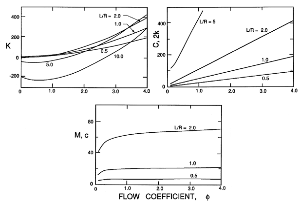
| Figure 10.6 Typical dimensionless rotordynamic coefficients from Childs' (1983a) analysis of a plain, untapered and smooth annular seal with δ/R=0.01, ReV=5000, and CEL=0.1. |
|
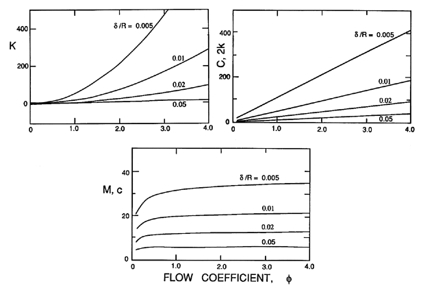
| Figure 10.7 Typical dimensionless rotordynamic coefficients from Childs' (1983a) analysis of a plain, untapered and smooth annular seal with L/R=1, ReV=5000, and CEL=0.1. |
The results obtained by Black and Jensen (1970) are similar to the above except for the expressions for some of the λ and μ quantities. Childs (1983a) contrasts the two sets of expressions, and observes that one of the primary discrepancies is that the Black and Jensen expressions yield a significant smaller added mass, M. We should also note that Childs (1983a) includes the effect of inlet preswirl which has a significant influence on the rotordynamic coefficients. Preswirl was not included in the results presented above.
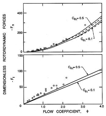
Typical results from the expressions 10.55 to 10.57 are presented in figures 10.6 and 10.7, which show the variations with flow coefficient, φ, and the geometric ratios, L/R and δ/R. The effects of Reynolds number, ReV, and of the entrance loss coefficient, are small as demonstrated in figure 10.8. Note the changes in sign in the direct stiffness, K, that result from the Lomakin effect becoming larger than the Bernoulli effect, or vice-versa. Note, also, that the whirl ratio, k/C, is 0.5 in all cases.
|
| Figure 10.8 The measurements by Childs and Dressman (1982) of the rotordynamic forces for a straight, smooth annular seal (L/R=1.0, δ/R=0.01) for a range of Reynolds numbers, 2205 < ReV < 13390, and under synchronous excitation. Also shown are the predictions of the theory of Childs (1983a) for ReV=10000 (solid lines) and 15000 (dashed lines) and two different entrance loss coefficients, CEL, as shown. |
Childs and Dressman (1982) have published experimental measurements of the rotordynamic forces in a plain, smooth, annular seal with a length, L, to radius, R, ratio of 1.0, a clearance, δ, to radius ratio of 0.01 at various flow rates and speeds. The excitation was synchronous (ω/Ω=1) so that
 | ......(10.66) |
 | ......(10.67) |
|
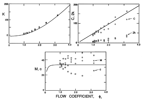
| Figure 10.9 Dimensionless rotordynamic coefficients measured by Nordmann and Massmann (1984) for a plain seal with L/R=1.67, δ/R=0.0167, and ReV=5265. Also shown are the corresponding theoretical results using Childs' (1983a) theory with CEL=0.1. |
Nordmann and Massman (1984) conducted experiments on a similar plain annular seal with L/R=1.67 and δ/R=0.0167, and measured the forces for both synchronous and nonsynchronous excitation. Thus, they were able to extract the rotordynamic coefficients M, C, c, K, and k. Their results for a Reynolds number, ReV=5265, are presented in figure 10.9, where they are compared with the corresponding predictions of Childs' (1983a) theory (using CEL=0.1). In comparing theory and experiment, we must remember that the results are quite insensitive to Reynolds number, and the theoretical data does not change much with changes in CEL. Some of the Nordmann and Massmann data exhibits quite a lot of scatter; however, with the notable exception of the cross-coupled stiffness, k, the theory is in good agreement with the data. The reason for the discrepancy in the cross-coupled stiffness is unclear. However, one must bear in mind that the theory uses correlations developed from results for nominally steady turbulent flows, and must be regarded as tentative until there exists a greater understanding of unsteady turbulent flows.
In the last decade, a substantial body of data has been accumulated on the rotordynamic characteristics of annular seals, particularly as regards such geometric effects as taper, various kinds of roughness, and the effects of labyrinths. We include here only a few examples. Childs and Dressman (1985) conducted both theoretical and experimental investigations of the effect of taper on the synchronous rotordynamic forces. They showed that the introduction of a taper increases the leakage and the direct stiffness, K*, but decreases the other rotordynamic coefficients. An optimum taper angle exists with respect to both the direct stiffness and the ratio of direct stiffness to leakage. Childs and Kim (1985) have examined the effects of directionally homogeneous surface roughness on both the rotor and the stator. Test results for four different surface roughnesses applied to the stator or casing (so-called ``damper seals'' that have smooth rotors) showed that the roughness increases the damping and decreases the leakage.
10.8 LABYRINTH SEALS
Labyrinth seals with teeth on either the rotor or the stator are frequently used, because the teeth help to minimize the leakage through the seals. However, the teeth also have rotordynamic consequences which have been explored by Wachter and Benckert (1980), Childs and Scharrer (1986), and others. Childs and Scharrer measured the stiffness and damping coefficients for some labyrinth seals, and reached the following conclusions. First, in all cases, the rotordynamic forces were independent of the rotational speed, Ω, and dependent on the axial pressure drop, Δp. The appropriate nondimensionalizing velocity is therefore the typical axial velocity caused by the axial pressure drop, (2Δp/ρ)½. Childs and Scharrer suggest that the reason for this behavior is that the mean fluid motions are dominated by throughflow over and between the teeth, and that the shear caused by the rotation of the rotor has relatively little effect on the flow at the high Reynolds numbers involved.
| Table 10.1 | ||||||
| Rotordynamic characteristics of labyrinth seals with zero inlet swirl | ||||||
| (data from Childs and Scharrer 1986) | ||||||
| Teeth on Rotor | Teeth on Stator | |||||
| Mean | Min. | Max. | Mean | Min. | Max. | |
| K*/ 2πΔp L | -1.17 | -1.03 | -1.25 | -0.62 | -0.45 | -0.74 |
| k*/ 2πΔp L | 1.15 | 0.79 | 1.68 | 0.86 | 0.67 | 1.07 |
| C*/π RL(2ρΔp)½ | 0.0225 | 0.0168 | 0.0279 | 0.0219 | 0.0182 | 0.0244 |
Typical dimensionless values of the rotordynamic coefficients K, k, and C are presented in table 10.1, where we may observe that the cross-coupled stiffness, k, is smaller for the teeth-on-stator configuration. This means that, since the damping, C, is similar for the two cases, the teeth-on-stator configuration is more stable rotordynamically.
However, Childs and Scharrer also found that the coefficients were very sensitive to the inlet swirl velocity upstream of the seal. In particular, the cross-coupled stiffness increased markedly with increased swirl in the same direction as shaft rotation. On the other hand, imposed swirl in a direction opposite to shaft rotation causes a reversal in the sign of the cross-coupled stiffness, and thus has a rotordynamically stabilizing effect.
10.9 BLADE TIP ROTORDYNAMIC EFFECTS
In a seminal paper, Alford (1965) identified several rotordynamic effects arising from the flow in the clearance region between the tip of an axial flow turbomachine blade and the static housing. However, the so-called ``Alford effects'' are only some of the members of a class of rotordynamic phenomena that can arise from the fluid-induced effects of a finite number of blades, and, in this section, we shall first examine the more general class of phenomena.
|
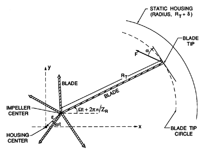
| Figure 10.10 Schematic of the position of an axial flow turbomachine blade tip relative to a static housing as a result of the combination of rotational and whirl motion (details shown for only one of the Zr blade tips). |
Consider the typical geometry of an unshrouded impeller of radius RT and ZR blades enclosed by a cylindrical housing so that the mean clearance between the blade tips and the housing is δ (figure 10.10). If the impeller is rotating at a frequency, Ω, and whirling at a frequency, ω, with an amplitude, ε, then the vector positions of the blade tips at time, t, will be given by
 | ......(10.68) |
 | ......(10.69) |
Next, the most general form of the force, F*, acting on the tip of the blade is
 | ......(10.70) |
 | ......(10.71) |
One choice of the form of F and α corresponds to the Alford effect. Alford (1965) surmised that the fluid force acting normal to each blade (α=0 or π) would vary according to the instantaneous tip clearance of that blade. Specifically, he argued that an increase in the clearance, ε cosθn, would produce a proportionate decrease in the normal force, or
 | ......(10.72) |
 is the factor of proportionality.
Moreover, for a pump
α=π, and for a turbine α=0. Substituting
these values into equation 10.70, one obtains
 | ......(10.73) |
As a second, but more theoretical example, consider the added mass effect that occurs when a blade tip approaches the casing and squeezes fluid out from the intervening gap. Such a flow would manifest a force on the blade proportional to the acceleration d2δ*/dt2, so that
 | ......(10.74) |
 is some different proportionality factor.
It follows from equation 10.71 that, in this case,
 | ......(10.75) |
Other tip clearance flow effects, such as those due to viscous or frictional effects, can be investigated using the general result in equation 10.71, as well as appropriate choices for α and F.
10.10 STEADY RADIAL FORCES
We now change the focus of attention back to pumps, and, more specifically, to the kinds of radial and rotordynamic forces which may be caused by the flow through and around an impeller. Unlike some of the devices discussed in the preceding sections, the flow through a pump can frequently be nonaxisymmetric and so can produce a mean radial force that can be of considerable importance. The bearings must withstand this force, and this can lead to premature bearing wear and even failure. Bearing deflection can also cause displacement of the axis of rotation of the impeller, that may, in turn, have deleterious effects upon hydraulic performance. The existence of radial forces, and attempts to evaluate them, date back to the 1930s (see Stepanoff's comment in Biheller 1965) or earlier.
|
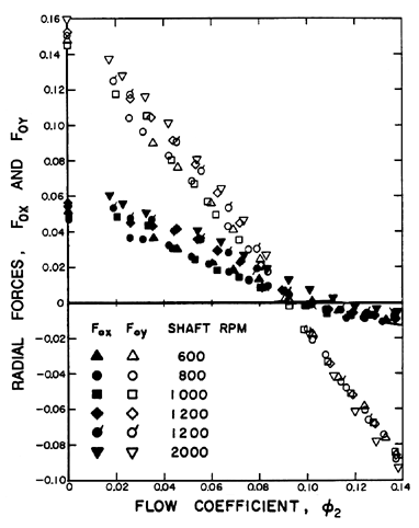
| Figure 10.11 Radial forces for the centrifugal Impeller X/Volute A combination as a function of shaft speed and flow coefficient (Chamieh et al. 1985). |
|
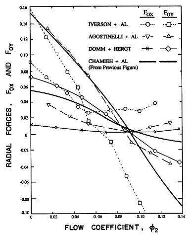
| Figure 10.12 Comparison of the radial forces measured by Iverson, Rolling and Carlson (1960) on a pump with a specific speed, ND, of 0.36, by Agostinelli, Nobles and Mockeridge (1960), on a pump with ND=0.61, by Domm and Hergt (1970), and by Chamieh et al. (1985) on a pump with ND=0.57. |
The nonaxisymmetries and, therefore, the radial forces depend upon the geometry of the diffuser and/or volute as well as the flow coefficient. Measurements of radial forces have been made with a number of different impeller/diffuser/volute combinations by Agostonelli et al. (1960), Iverson et al. (1960), Biheller (1965), Grabow (1964), and Chamieh et al. (1985), among others. Stepanoff (1957) proposed an empirical formula for the magnitude of the nondimensional radial force,
 | ......(10.76) |
 | ......(10.77) |
Some typical nondimensional radial forces obtained experimentally by Chamieh et al. (1985) for the Impeller X/Volute A combination (see section 2.8) are shown in figure 10.11 for a range of speeds and flow coefficients. First note that, as anticipated in the nondimensionalization, the radial forces do indeed scale with the square of the impeller speed. This implies that, at least within the range of rotational speeds used for these experiments, the Reynolds number effects on the radial forces are minimal. Second, focusing on Chamieh's data, it should be noted that the ``design'' objective that Volute A be well matched to Impeller X appears to be satisfied at a flow coefficient, φ2, of 0.092 where the magnitude of the radial force appears to vanish.
|
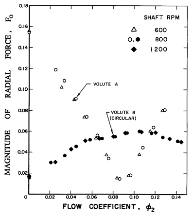
| Figure 10.13 Comparison of the magnitude of the radial force (F0) on Impeller X caused by Volute A and by the circular Volute B with a circumferentially uniform area (Chamieh et al. 1985). |
Other radial force data are presented in figure 10.12. The centrifugal pump tested by Agostinelli, Nobles and Mockeridge (1960) had a specific speed, ND, of 0.61, and was similar to that of Chamieh et al. (1985). On the other hand, the pump tested by Iversen, Rolling and Carlson (1960) had a much lower specific speed of 0.36, and the data of figure 10.12 indicates that their impeller/volute combination is best matched at a flow coefficient of about 0.06. The data of Domm and Hergt (1970) is for a volute similar to Volute A and, while qualitatively similar to the other data, has a significantly smaller magnitude than the other three sets of data. The reasons for this are not clear.
|
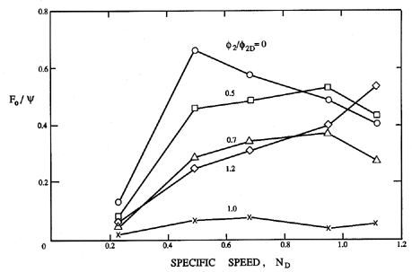
| Figure 10.14 Variation of the radial force magnitude, F0, divided by the head coefficient, ψ, as a function of specific speed, ND, and flow for a class of volute casing pumps (adapted from KSB 1975). |
The dependence of the radial forces on volute geometry is illustrated in figure 10.13 from Chamieh et al. (1985) which presents a comparison of the magnitude of the force on Impeller X due to Volute A with the magnitude of the force due to a circular volute with a circumferentially uniform cross-sectional area. In theory, this second volute could only be well-matched at zero flow rate; note that the results do exhibit a minimum at shut-off. Figure 10.13 also illustrates one of the compromises that a designer may have to make. If the objective were to minimize the radial force at a single flow rate, then a well-designed spiral volute would be appropriate. On the other hand, if the objective were to minimize the force over a wide range of flow rates, then a quite different design, perhaps even a constant area volute, might be more effective. Of course, a comparison of the hydraulic performance would also have to be made in evaluating such design decisions. Note from figure 7.1 that the spiral volute is hydraulically superior up to a flow coefficient of 0.10 above which the results are circular volute is superior.
 <
< |
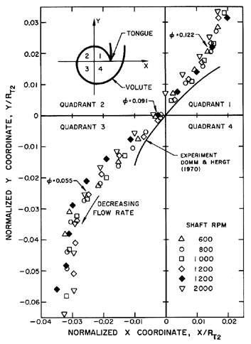
| Figure 10.15 Locus of the zero radial force locations for the Impeller X/Volute A combination (Chamieh et al. 1985) compared with that from the data of Domm and Hergt (1970). |
As further information on the variation of the magnitude of the radial forces in different types of pump, we include figure 10.14, taken from KSB (1975), which shows how F0/ψ may vary with specific speed and flow rate for a class of volute pumps. The magnitudes of the forces shown in this figure are larger than those of figure 10.12. We should also note that the results of Jery and Franz (1982) indicate that the presence of diffuser vanes (of typical low solidity) between the impeller discharge and the volute has relatively little effect on the radial forces.
It is also important to recognize that small changes in the location of the impeller within the volute can cause large changes in the radial forces. This gradient of forces is represented by the hydrodynamic stiffness matrix, [K] (see section 10.2), for which data will be presented in the context of the rotordynamic coefficients. The dependence of the radial force on the impeller position also implies that, for a given impeller/volute combination at a particular flow coefficient, there exists a particular location of the axis of impeller rotation for which the radial force is zero. As an example, the locus of zero radial force positions for the Impeller X/Volute A combination is presented in figure 10.15. Note that this location traverses a distance of about 10% of the impeller radius as the flow rate increases from zero to a flow coefficient of 0.14.
|
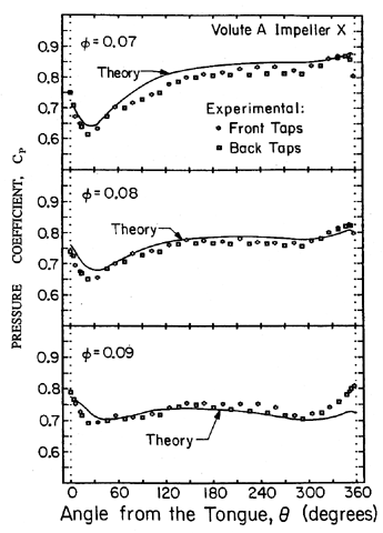
| Figure 10.16 Circumferential pressure distributions in the impeller discharge for the Impeller X/Volute A combination at three different flow rates. Also shown are the theoretical pressure distributions of Adkins and Brennen (1988). |
Visualizing the centrifugal pump impeller as a control volume, one can recognize three possible contributions to the radial force. First, circumferential variation in the impeller discharge pressure (or volute pressure) will clearly result in a radial force acting on the impeller discharge area. A second contribution could be caused by the leakage flow from the impeller discharge to the inlet between the impeller shroud and the pump casing. Circumferential nonuniformity in the discharge pressure could cause circumferential nonuniformity in the pressure within this shroud-casing gap, and therefore a radial force acting on the exterior of the pump shroud. For convenience, we shall term this second contribution the leakage flow contribution. Third, a circumferential nonuniformity in the flow rate out of the impeller would imply a force due to the nonuniformity in the momentum flux out of the impeller. This potential third contribution has not been significant in any of the studies to date. Both the first two contributions appear to be important.
|
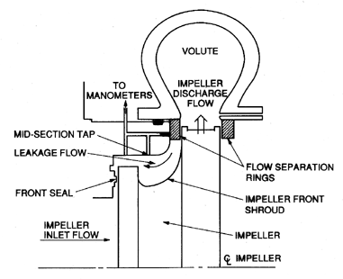
| Figure 10.17 Schematic of the Impeller X/Volute A arrangement used for the experiments of Chamieh et al. (1985) and Adkins and Brennen (1988). |
In order to investigate the origins of the radial forces, Adkins and Brennen (1988) (see also Brennen et al. 1986) made measurements of the pressure distributions in the volute, and integrated these pressures to evaluate the contribution of the discharge pressure to the radial force. Typical pressure distributions for the Impeller X/Volute A combination (with the flow separation rings of figure 10.17 installed) are presented in figure 10.16 for three different flow coefficients. Minor differences occur in the pressures measured in the front sidewall of the volute at the impeller discharge (front taps) and those in the opposite wall (back taps).
|
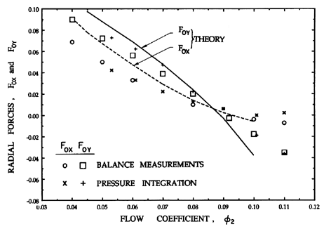
| Figure 10.18 Comparison of radial forces from direct balance measurements, from integration of measured pressures, and from theory for the Impeller X/Volute A combination (from Adkins and Brennen 1988). |
The experimental measurements in figure 10.18 are compared with theoretical predictions based on an analysis that matches a guided impeller flow model with a one-dimensional treatment of the flow in the volute. This same theory was used to calculate rotordynamic matrices and coefficients presented in section 10.12. In the present context, integration of the experimental pressure distributions yielded radial forces in good agreement with both the overall radial forces measured using the force balance and the theoretical predictions of the theory. These results demonstrate that it is primarily the circumferential nonuniformity in the pressure at the impeller discharge that generates the radial force. The theory clearly demonstrates that the momentum flux contribution is negligible.
The leakage flow from the impeller discharge, between the impeller shroud and the pump casing, and back to the pump inlet does make a significant contribution to the radial force. Figure 10.17 is a schematic of the impeller, volute, and casing used in the experiments of Chamieh et al. (1985) and Adkins and Brennen (1988), as well as for the rotordynamic measurements discussed later. Adkins and Brennen obtained data with and without the obstruction at the entrance to the leakage flow labelled ``flow separation rings''. The data of figures 10.16 and 10.18 were taken with these rings installed (whereas Chamieh's data was taken without the rings). The measurements showed that, in the absence of the rings, the nonuniformity in the impeller discharge pressure caused significant nonuniformity in the pressure in the leakage annulus, and, therefore, a significant contribution from the leakage flow to the radial force. This was not the case once the rings were installed, for the rings effectively isolated the leakage annulus from the impeller discharge nonuniformity. However, a compensating mechanism exists which causes the total radial force in the two cases to be more or less the same. The increased leakage flow without the rings tends to relieve some of the pressure nonuniformity in the impeller discharge, thus reducing the contribution from the impeller discharge pressure distribution.
A number of other theoretical models exist in the literature. The analysis of Lorett and Gopalakrishnan (1983) is somewhat similar in spirit to that of Adkins and Brennen (1988). Earlier analyses, such as those of Domm and Hergt (1970) and Colding-Jorgensen (1979), were based on modeling the impeller by a source/vortex within the volute and solutions of the resulting potential flow. They represent too much of a departure from real flows to be of much applicability.
Finally, we note that the principal focus of this section has been on radial forces caused by circumferential nonuniformity in the discharge conditions. It must be clear that nonuniformities in the inlet flow due, for example, to bends in the suction piping are also likely to generate radial forces. As yet, such forces have not been investigated. Moreover, it seems reasonable to suggest that inlet distortion forces are more likely to be important in axial inducers or pumps than in centrifugal pumps.
|
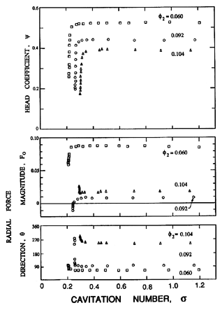
| Figure 10.19 Variation of the head and radial force (magnitude, F0, and direction, θ, measured from the cutwater) with cavitation number, σ, for Impeller X/Volute A at three flow coefficients and at 3000rpm (from Franz et al. 1990). |
10.11 EFFECT OF CAVITATION
Franz et al. (1990) (see also Brennen et al. 1988) have made measurements of the radial forces for the Impeller X/Volute A combination under cavitating conditions. These studies show that any loss of head can also cause major changes in the magnitude and direction of the radial force. This is illustrated in figure 10.19, where the cavitation performance is juxtaposed with the variation in the radial forces for three different flow coefficients. Note that the radial force changes when the head rise across the pump is affected by cavitation. Note also that the changes in the radial forces are large, in some instances switching direction by 180° while the flow rate remains the same. This result may be of considerable significance since pumps operating near breakdown often exhibit fluctuations in which the operating point moves back and forth over the knee of the cavitation performance curve. According to figure 10.19, such performance fluctuations would result in large fluctuating forces that could well account for the heavy vibration and rough running that is usually manifest by a pump operating under cavitating conditions.
10.12 CENTRIFUGAL PUMPS
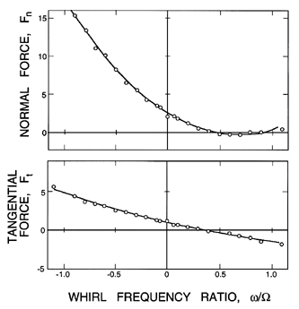
Rotordynamic forces in a centrifugal pump were first measured by Hergt and Krieger (1969-70), Ohashi and Shoji (1984b) and Jery et al. (1985). Typical data for the dimensionless normal and tangential forces, Fn and Ft, as a function of the frequency ratio, ω/Ω, are presented in figure 10.20 for the Impeller X/Volute A combination. The curve for Impeller X is typical of a wide range of results at different speeds, flow coefficients,
|
| Figure 10.20 Typical rotordynamic forces, Fn and Ft, as a function of whirl frequency ratio, ω/Ω, for the Impeller X/Volute A combination running at 1000rpm and a flow coefficient of φ2=0.092 (from Jery et al. 1985). |
and with different impellers and volutes. Perhaps the most significant feature of these results is that there exists a range of whirl frequencies for which the tangential force is whirl destabilizing. A positive Ft at negative whirl frequencies opposes the whirl motion, and is, therefore, stabilizing, and fairly strongly so since the forces can be quite large in magnitude. Similarly, at large, positive frequency ratios, the Ft is negative and is also stabilizing. However, between these two stabilizing regions, one usually finds a regime at small positive frequency ratios where Ft is positive and therefore destabilizing.
As is illustrated by figure 10.20, the variation of Fn and Ft with the whirl frequency ratio, ω/Ω, can be represented quite accurately by the quadratic expressions of equations 10.13 and 10.14 (this is not true for axial flow pumps, as will be discussed later). The rotordynamic coefficients, obtained from data like that of figure 10.20 for a wide variety of speeds, flow rates, and impeller, diffuser, and volute geometries, are given in table 10.2 (adapted from Jery et al. 1985). Note, first, some of the general characteristics of these coefficients. The direct stiffness, K, is always negative because of the Bernoulli effect (see section 10.3). The cross-coupled stiffness, k, is always positive, and is directly connected to the positive values of Ft at low positive whirl frequency ratios; consequently, k is a measure of the destabilizing effect of the fluid. The direct damping, C, is positive, but usually less than half of the value of the cross-coupled damping, c. Note that the value of k/C is usually a fairly accurate measure of the whirl frequency ratio corresponding to the upper bound of the destabilizing interval of whirl frequency ratios. From table 10.2 the values of k/C, for actual impellers with volutes and with nonzero flow, range from 0.25 to 0.40, so the range of subsynchronous speeds, for which these fluid forces are destabilizing, can be quite large. Resuming the summary of the rotordynamic coefficients, note that the cross-coupled added mass, m, is small in comparison with the direct added mass, M, and can probably be neglected in many applications. Note that, since the direct added mass is converted to dimensional form by πρR2T2B2, it follows that typical values of the added mass, M, are equivalent to the mass of about six such cylinders, or about five times the volume of liquid inside the impeller.
| Table 10.2 | ||||||||
| Rotordynamic coefficients for various centrifugal pump configurations (from Jery et al. 1985). Volute E is a 17-bladed diffuser with a spiral volute. Volutes D, F, G and H are spiral volutes fitted with zero, 6, 6 and 12 vanes respectively. Impeller Y is a 6-bladed impeller. Impeller S is a solid mass with the same external profile as Impeller X. | ||||||||
| Impeller/Volute | rpm | φ2 | K | k | C | c | M | m |
| Imp.X/Volute A | 500 | 0.092 | -2.51 | 1.10 | 3.14 | 7.91 | 6.52 | -0.52 |
| 1000 | 0.092 | -2.61 | 1.12 | 3.28 | 8.52 | 6.24 | -0.53 | |
| 1500 | 0.092 | -2.47 | 0.99 | 3.00 | 8.71 | 6.87 | -0.87 | |
| 2000 | 0.092 | -2.64 | 1.15 | 2.91 | 9.06 | 7.02 | -0.67 | |
| Imp.X/Volute E | 1000 | 0 | -1.64 | 0.14 | 3.40 | 7.56 | 6.83 | 0.68 |
| 1000 | 0.060 | -2.76 | 1.02 | 3.74 | 9.53 | 6.92 | -1.01 | |
| 1000 | 0.092 | -2.65 | 1.04 | 3.80 | 8.96 | 6.60 | -0.90 | |
| 1000 | 0.145 | -2.44 | 1.16 | 4.11 | 7.93 | 6.20 | -0.55 | |
| Imp.X/none | 1000 | 0.060 | -0.55 | 0.67 | 1.24 | 3.60 | 4.38 | 1.68 |
| Imp.X/Volute D | 1000 | 0.060 | -2.86 | 1.12 | 2.81 | 9.34 | 6.43 | -0.15 |
| Imp.X/Volute F | 1000 | 0.060 | -3.40 | 1.36 | 3.64 | 9.51 | 6.24 | -0.72 |
| Imp.X/Volute G | 1000 | 0.060 | -3.34 | 1.30 | 3.42 | 9.11 | 5.75 | -0.39 |
| Imp.X/Volute H | 1000 | 0.060 | -3.42 | 1.33 | 3.75 | 10.34 | 7.24 | -0.65 |
| Imp.Y/Volute E | 1000 | 0.092 | -2.81 | 0.85 | 3.34 | 8.53 | 5.50 | -0.74 |
| Imp.S/Volute A | 1000 | -0.42 | 0.41 | 1.87 | 3.81 | 6.54 | -0.04 | |
Now examine the variations in the values of the rotordynamic coefficients in table 10.2. The first series of data clearly demonstrates that the nondimensionalization has satisfactorily accounted for the variation with rotational speed. Any separate effect of Reynolds number does not appear to occur within the range of speeds in these experiments. The second series in table 10.2 illustrates the typical variations with flow coefficient. Note that, apart from the stiffness at zero flow, the coefficients are fairly independent of the flow coefficient. The third series utilized diffusers with various numbers and geometries of vanes inside the same volute. The presence of vanes appears to cause a slight increase in the stiffness; however, the number and type of vanes do not seem to matter. Note that, in the absence of any volute or diffuser, all of the coefficients (except m) are substantially smaller. Ohashi and Shoji (1984b) made rotordynamic measurements within a much larger volute than any in table 10.2; consequently their results are comparable with those given in table 10.2 for no volute. On the other hand, Bolleter, Wyss, Welte, and Sturchler (1985, 1987) report rotordynamic coefficients very similar in magnitude to those of table 10.2.
The origins of the rotordynamic forces in typical centrifugal pumps have been explored by Jery et al. (1985) and Adkins and Brennen (1988), among others. In order to explore the effect of the discharge-to-suction leakage flow between the shroud and the casing, Jery et al. (1985) compared the rotordynamic forces generated by the Impeller X/Volute A combination with those generated in the same housing by a dummy impeller (Impeller S) with the same exterior profile as Impeller X. A pressure difference was externally applied in order to simulate the same inlet to discharge static pressure rise, and, therefore, produce a leakage flow similar to that in the Impeller X experiments. As in the case of the radial forces, we surmise that unsteady circumferential pressure differences on the impeller discharge and in the leakage flow can both contribute to the rotordynamic forces on an impeller. As can be seen from the coefficients listed in table 10.2, the rotordynamic forces with the dummy impeller represented a substantial fraction of those with the actual impeller. We conclude that the contributions to the rotordynamic forces from the unsteady pressures acting on the impeller discharge and those from the unsteady pressures in the leakage flow acting on the shroud are both important and must be separately investigated and evaluated.
|
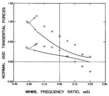
| Figure 10.21 Comparison of the rotordynamic force contributions due to the impeller discharge pressure variations as predicted by the theory of Adkins and Brennen (1988) (solid lines) with experimental measurements using Impeller X and Volute A (at φ2=0.092) but with the casing surrounding the front shroud removed to mimimize the leakage flow contributions. |
We focus first on the impeller discharge contribution. Adkins and Brennen (1988) used an extension of the theoretical model described briefly in section 10.10 to evaluate the rotordynamic forces acting on the impeller discharge. They also made measurements of the forces for an Impeller X/Volute A configuration in which the pump casing structure external to the shroud was removed in order to minimize any contributions from the leakage flow. The resulting experimental and theoretical values of Fn and Ft are presented in figure 10.21. First note that these values are significantly smaller than those of figure 10.20, indicating that the impeller discharge contributions are actually smaller than those from the leakage flow. Second note that the theory of Adkins and Brennen (1988) provides a reasonable estimate of the impeller discharge contribution to the rotordynamic forces, at least within the range of whirl frequencies examined.
Using the Impeller X/Volute A configuration, Adkins and Brennen also made experimental measurements of the pressure distributions in the impeller discharge flow and in the leakage flow. These measurements allowed calculations of the stiffnesses, K=Fn(0) and k=Ft(0). The results indicated that the leakage flow contributes about 70% of K and about 40% of k; these fractional contributions are similar to those expected from a comparison of figures 10.20 and 10.21.
About the same time, Childs (1987) used the bulk-flow model described in section 10.7 to evaluate the contributions to the rotordynamic forces from the discharge-to-suction leakage flow. While his results exhibit some peculiar resonances not yet observed experimentally, the general magnitude and form of Childs results are consistent with the current conclusions. More recently, Guinzberg et al. (1990) have made experimental measurements for a simple leakage flow geometry that clearly confirm the importance of the rotordynamic effects caused by these flows. They also demonstrate the variations in the leakage flow contributions with the geometry of the leakage path, the leakage flow rate and the swirl in the flow at the entrance to the leakage path.
It is important to mention previous theoretical investigations of the rotordynamic forces acting on impellers. A number of the early models (Thompson 1978, Colding-Jorgensen 1979, Chamieh and Acosta 1981) considered only quasistatic perturbations from the mean flow, so that only the stiffness can be evaluated. Ohashi and Shoji (1984a) (see also Shoji and Ohashi 1980) considered two-dimensional, inviscid and unseparated flow in the impeller, and solved the unsteady flow problem by singularity methods. Near the design flow rate, their results compare well with their experimental data, but at lower flows the results diverge. More recently, Tsujimoto et al. (1988) have included the effects of a volute; their two-dimensional analysis yielded good agreement with the measurements by Jery et al. (1985) on a two-dimensional impeller.
Finally, in view of the significant effect of cavitation on the radial forces (section 10.10), it is rather surprising to find that the effect of cavitation on the rotordynamic forces in centrifugal pumps seems to be quite insignificant (Franz et al. 1990).
10.13 MOMENTS AND LINES OF ACTION
|
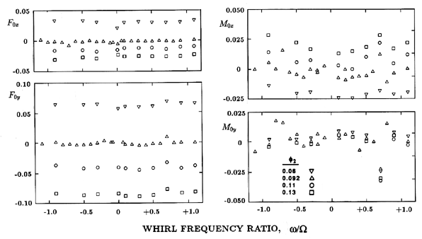
| Figure 10.22 Steady radial forces, F0x and F0y , and moments, M0x and M0y , for Impeller X/Volute A at a speed of 1000rpm and various flow coefficients as indicated (from Miskovish and Brennen 1992). |
|
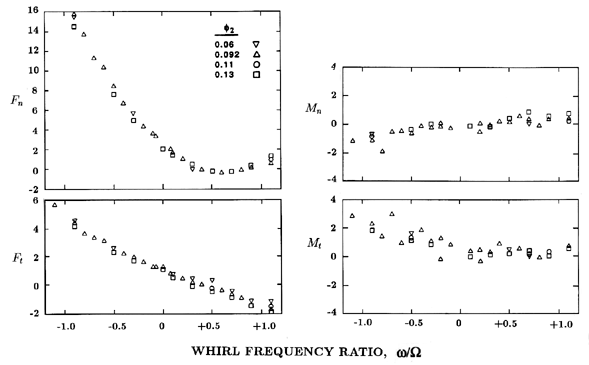
| Figure 10.23 Normal and tangential rotordynamic forces, Fn and Ft, and moments, Mn and Mt, for Impeller X/Volute A at 1000rpm and various flow coefficients as indicated (from Miskovish and Brennen 1992). |
Some data on the steady bending moments, M0x and M0y , and on the rotordynamic moments
 | ......(10.78) |
Typical sets of data taken from Miskovish and Brennen (1992) are presented in figures 10.22 and 10.23. These were obtained for the Impeller X/Volute A combination operating at a speed of 1000rpm. For convenience, the axial location of the origin of the reference coordinate system has been placed at the center of the impeller discharge. Since the lines of action of the forces are not too far from this location, the moments presented here are small, and, for this reason, the data for the moments is somewhat scattered.
Steady forces and moments are presented for many whirl frequency ratios in figure 10.22. These forces and moments should, of course, be independent of the whirl frequency ratio, and so the deviation of the data points from the mean for a given flow coefficient represents a measure of the scatter in the data. Despite this scatter, the moment data in figure 10.22 does suggest that a nonzero steady moment is present, and that it changes with flow coefficient. The typical location for the line of action of F0, which this data implies, may be best illustrated by an example. At φ=0.06, the steady vector force F0 has a magnitude of 0.067 (F0x approximately 0.03, F0y approximately 0.06) and an angle θF=63° from the x-axis. The corresponding moment vector has a magnitude of 0.02 and an angle, θM, about 180° from the x-axis. Consequently, the line of action of F0 is an axial distance upstream of the origin equal to 0.02 sin(180-63)/0.067=0.27. In other words, the line of action is about a quarter of a discharge radius upstream of the center of the discharge. This is consistent with the previous observation (section 10.10) that the pressures acting on the exterior of the shroud also contribute to the steady radial forces; this contribution displaces the line of action upstream of the center of the discharge.
The data of figure 10.23 could be similarly used to evaluate the lines of action of the rotordynamic forces whose components are Fn and Ft. However, the moments Mn and Mt are small over most of the range of whirl ratios, and lead to lines of action that are less than 0.1 of a radius upstream of the center of the discharge in most cases. This is consistent with other experiments on this same impeller/volute/casing combination that suggest that the shroud force contribution to the rotordynamic matrices is smaller than the impeller discharge contribution in this particular case.
10.14 AXIAL FLOW INDUCERS
|
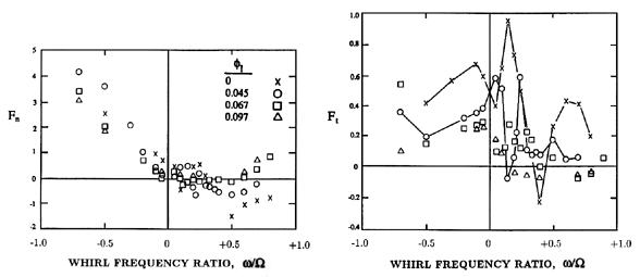
| Figure 10.24 Rotordynamic forces for the helical inducer, Impeller VII, for four different flow coefficients (from Arndt and Franz 1986). |
The rotordynamic forces in an unshrouded axial flow pump, or those caused by adding an axial inducer to a centrifugal pump, are less well understood. One of the reasons for this is that the phenomena will depend on the dynamic response of the tip clearance flows, an unsteady flow that has not been studied in any detail. The experimental data that does exist (Franz and Arndt 1986, Arndt and Franz 1986, Karyeaclis et al. 1989) clearly show that important and qualitatively different effects are manifest by unshrouded axial flow pumps. These effects were not encountered with shrouded centrifugal impellers. They are exemplified by figure 10.24, which presents data on Fn and Ft for the 9° helical inducer, Impeller VII, tested alone at a series of flow coefficients (Arndt and Franz 1986). At the higher flow coefficients, the variation of Fn and Ft with whirl frequency ratio, ω/Ω, is similar to the centrifugal pump data. However, as the flow coefficient is decreased, somewhat pathological behavior begins to appear in the values of Ft (and to a lesser degree Fn) at small and positive whirl frequency ratios. This culminates in extremely complicated behavior at shut-off (zero flow) in which Ft changes sign several times for positive whirl frequency ratios, implying several separate regions of destabilizing fluid-induced rotordynamic effect. Note that the maximum values of Ft that were recorded, are large, and could well be responsible for significant vibration in an axial flow pump or inducer. Similar pathological rotordynamic effects were encountered with all the axial inducers tested, including the inducer/impeller combination represented by the high pressure LOX pump in the Space Shuttle Main Engine (Franz and Arndt 1986). However, the details in the variations of Ft with ω/Ω differed from one inducer to another.
Finally, we should note that the current codes for rotordynamic investigations are not well adapted to deal with deviations from the quadratic forms for F*n and F*t given in equations 10.13 and 10.14. Consequently, more remains to be done in terms of rotordynamic analysis before the implications of such complex frequency-dependent behavior of F*n and F*t become clear.
- Adkins, D.R. and Brennen, C.E. (1988). Analyses of hydrodynamic radial forces on centrifugal pump impellers. ASME J. Fluids Eng., 110, No. 1, 20--28.
- Agostinelli, A., Nobles, D. and Mockridge, C.R. (1960). An experimental investigation of radial thrust in centrifugal pumps. ASME J. Eng. for Power, 82, 120--126.
- Alford, J.S. (1965). Protecting turbomachinery from self-excited rotor whirl. ASME. J. Eng. for Power, 87, 333--344.
- Arndt, N. and Franz, R. (1986). Observations of hydrodynamic forces on several inducers including the SSME LPOTP. Calif. Inst. of Tech., Div. Eng. and Appl. Sci., Report No. E249.3.
- Biheller, H.J. (1965). Radial force on the impeller of centrifugal pumps with volute, semi-volute and fully concentric casings. ASME J. Eng. for Power, July 1965, 319--323.
- Black, H.F. (1969). Effects of hydraulic forces in annular pressure seals on the vibrations of centrifugal pump rotors. J. Mech. Eng. Sci., 11, No. 2, 206--213.
- Black, H.F. and Jensen, D.N. (1970). Dynamic hybrid properties of annular pressure seals. Proc. J. Mech. Eng., 184, 92--100.
- Bolleter, U., Wyss, A., Welte, I., and Sturchler, R. (1985). Measurements of hydrodynamic interaction matrices of boiler feed pump impellers. ASME Paper No. 85-DET-148.
- Bolleter, U., Wyss, A., Welte, I., and Sturchler, R. (1987). Measurement of hydrodynamic matrices of boiler feed pump impellers. ASME J. Vibrations, Stress and Reliability in Design, 109, 144--151.
- Brennen, C. (1976). On the flow in an annulus surrounding a whirling cylinder. J. Fluid Mech., 75, 173--191.
- Brennen, C.E., Acosta, A.J., and Caughey, T.K. (1986). Impeller fluid forces. Proc. NASA Advanced Earth-to-Orbit Propulsion Technology Conference, Huntsville, AL, NASA Conf. Publ. 2436, 270-295.
- Brennen, C.E., Franz, R. and Arndt, N. (1988). Effects of cavitation on rotordynamic force matrices. Proc. NASA Advanced Earth-to-Orbit Propulsion Technology Conference, Huntsville, AL, NASA Conf. Publ. 3012, 227--239.
- Chamieh, D.S. and Acosta, A.J. (1981). Calculation of the stiffness matrix of an impeller eccentrically located within a volute. Proc. ASME Cavitation and Polyphase Flow Forum, 51--53.
- Chamieh, D.S., Acosta, A.J., Brennen, C.E., and Caughey, T.K. (1985). Experimental measurements of hydrodynamic radial forces and stiffness matrices for a centrifugal pump-impeller. ASME J. Fluids Eng., 107, No. 3, 307--315.
- Childs, D.W. (1983a). Dynamic analysis of turbulent annular seals based on Hirs' lubrication equation. ASME J. Lubr. Tech., 105, 429--436.
- Childs, D.W. (1983b). Finite length solutions for rotordynamic coefficients of turbulent annular seals. ASME J. Lubr. Tech., 105, 437--445.
- Childs, D.W. (1987). Fluid structure interaction forces at pump-impeller-shroud surfaces for rotordynamic calculations. ASME Symp. on Rotating Machinery Dynamics, 2, 581--593.
- Childs, D.W. (1989). Fluid structure interaction forces at pump-impeller-shroud surfaces for rotordynamic calculations. ASME J. Vibration, Acoustics, Stress and Reliability in Design, 111, 216--225.
- Childs, D.W. and Dressman, J.B. (1982). Testing of turbulent seals for rotordynamic coefficients. Proc. Workshop on Rotordynamic Instability Problems in High-Performance Turbomachinery, NASA Conf. Publ. 2250, 157--171.
- Childs, D.W. and Dressman, J.B. (1985). Convergent-tapered annular seals: analysis and testing for rotordynamic coefficients. ASME J. Tribology, 107, 307--317.
- Childs, D.W. and Kim, C.-H. (1985). Analysis and testing for rotordynamic coefficients of turbulent annular seals with different directionally homogeneous surface roughness treatment for rotor and stator elements. ASME J. Tribology, 107, 296--306.
- Childs, D.W. and Scharrer, J.K. (1986). Experimental rotordynamic coefficient results for teeth-on-rotor and teeth-on-stator labyrinth gas seals. Proc. Adv. Earth-to-Orbit Propulsion Tech. Conf., NASA Conf. Publ. 2436, 327--345.
- Colding-Jorgensen, J. (1979). The effect of fluid forces on rotor stability of centrifugal compressors and pumps. Ph.D. Thesis, Tech. Univ. of Denmark.
- Domm, H. and Hergt, P. (1970). Radial forces on impeller of volute casing pumps. In Flow Research on Blading (ed: L.S. Dzung), Elsevier Publ. Co., 305--321.
- Dowson, D. and Taylor, C.M. (1979). Cavitation in bearings. Ann. Rev. Fluid Mech., 11, 35--66.
- Doyle, H.E. (1980). Field experiences with rotordynamic instability in high-performance turbomachinery. Proc. First Workshop on Rotordynamic Instability Problems in High-Performance Turbomachinery, NASA Conf. Pub. 2133, 3--13.
- Duncan, A.B. (1966). Vibrations in boiler feed pumps: a critical review of experimental and service experience. Proc. Inst. Mech. Eng., 181, 55--64.
- Ehrich, F. and Childs, D. (1984). Self-excited vibration in high-performance turbomachinery. Mech. Eng., May 1984, 66--79.
- Ek, M.C. (1978). Solution of the subsynchronous whirl problem in the high pressure hydrogen turbomachinery of the Space Shuttle Main Engine. Proc. AIAA/SAE 14th Joint Propulsion Conf., Las Vegas, Nevada, Paper No. 78-1002.
- France, D. (1986). Rotor instability in centrifugal pumps. Shock and Vibr. Digest of Vibr. Inst., Jan.1986, 9--13.
- Franz, R. and Arndt, N. (1986). Measurements of hydrodynamic forces on the impeller of the HPOTP of the SSME. Calif. Inst. of Tech., Div. Eng. and Appl. Sci., Report No. E249.
- Franz, R., Acosta, A.J., Brennen, C.E., and Caughey, T.K. (1990). The rotordynamic forces on a centrifugal pump impeller in the presence of cavitation. ASME J. Fluids Eng., 112, 264--271.
- Fritz, R.J. (1970). The effects of an annular fluid on the vibrations of a long rotor. Part I---Theory and Part II---Test. ASME J. Basic Eng., 92, 923--937.
- Grabow, G. (1964). Radialdruck bei Kreiselpumpen. Pumpen und Verdichter, No. 2, 11--19.
- Guinzburg, A., Brennen, C.E., Acosta, A.J., and Caughey, T.K. (1990). Measurements of the rotordynamic shroud forces for centrifugal pumps. Proc. ASME Turbomachinery Forum, FED-96, 23--26.
- Hergt, P. and Krieger, P. (1969-70). Radial forces in centrifugal pumps with guide vanes. Proc. Inst. Mech. Eng., 184, Part 3N, 101--107.
- Hirs, G.G. (1973). A bulk-flow theory for turbulence in lubricant films. ASME J. of Lubr. Tech., April 1973, 137--146.
- Hori, Y. (1959). A theory of oil whip. ASME J. Appl. Mech., June 1959, 189--198.
- Iversen, H.W., Rolling, R.E., and Carlson, J.J. (1960). Volute pressure distribution, radial force on the impeller and volute mixing losses of a radial flow centrifugal pump. ASME J. Eng. for Power, 82, 136--144.
- Jery, B. and Franz, R. (1982). Stiffness matrices for the Rocketdyne diffuser volute. Calif. Inst. of Tech., Div. Eng. and Appl. Sci., Report No. E249.1.
- Jery, B., Acosta, A.J., Brennen, C.E., and Caughey, T.K. (1985). Forces on centrifugal pump impellers. Proc. Second Int. Pump Symp., Houston, Texas, 21--32.
- Karyeaclis, M.P., Miskovish, R.S., and Brennen, C.E. (1989). Rotordynamic tests in cavitation of the SEP inducer. Calif. Inst. of Tech., Div. of Eng. and Appl. Sci., Report E200.27.
- KSB. (1975). KSB Centrifugal pump lexicon. Klein, Schanzlin and Becker, Germany.
- Lomakin, A.A. (1958). Calculation of the critical speed and the conditions to ensure dynamic stability of the rotors in high pressure hydraulic machines, taking account of the forces in the seals (in Russian). Energomashinostroenie, 14, No.4, 1--5.
- Lorett, J.A. and Gopalakrishnan, S. (1983). Interaction between impeller and volute of pumps at off-design conditions. Proc. ASME Symp. on Performance Characteristics of Hydraulic Turbines and Pumps, FED-6, 135--140.
- Makay, E. and Szamody, O. (1978). Survey of feed pump outages. Electric Power Res. Inst. Rep. FP-754.
- Marscher, W.D. (1988). Subsynchronous vibration in boiler feed pumps due to stable response to hydraulic forces at part-load. Proc. I.Mech.E. Conf. on Part Load Pumping, London, 167--175.
- Miskovish, R.S. and Brennen, C.E. (1992). Some unsteady fluid forces measured on pump impellers. ASME J. Fluids Eng., 114, 632--637.
- Newkirk, B.L. and Taylor, H.D. (1925). Shaft whipping due to oil action in journal bearing. General Electric Review, Aug. 1925, 559-568.
- Nordmann, R. and Massmann, H. (1984). Identification of dynamic coefficients of annular turbulent seals. Proc. Workshop on Rotordynamic Instability Problems in High-Performance Turbomachinery, NASA Conf. Publ. 2338, 295--311.
- Ohashi, H. and Shoji, H. (1984a). Theoretical study of fluid forces on whirling centrifugal impeller (in Japanese). Trans. JSME, 50, No. 458 B, 2518--2523.
- Ohashi, H. and Shoji, H. (1984b). Lateral fluid forces acting on a whirling centrifugal impeller in vaneless and vaned diffuser. Proc. Workshop on Rotordynamic Instability Problems in High Performance Turbomachinery, NASA Conf. Publ. 2338, 109--122.
- Pinkus, O. and Sternlicht, B. (1961). Theory of hydrodynamic lubrication. McGraw-Hill, New York.
- Pollman, E., Schwerdtfeger, H., and Termuehlen, H. (1978). Flow excited vibrations in high pressure turbines (steam whirl). ASME J. Eng. for Power, 100, 219--228.
- Rosenmann, W. (1965). Experimental investigations of hydrodynamically induced shaft forces with a three bladed inducer. Proc. ASME Symp. on Cavitation in Fluid Machinery, 172--195.
- Shoji, H. and Ohashi, H. (1980). Fluid forces on rotating centrifugal impeller with whirling motion. Proc. First Workshop on Rotordynamic Instability Problems in High-Performance Turbomachinery, NASA Conf. Pub. 2133, 317--328.
- Stepanoff, A.J. (1957). Centrifugal and axial flow pumps. John Wiley and Sons, Inc., New York.
- Thompson, W.E. (1978). Fluid dynamic excitation of centrifugal compressor rotor vibrations. ASME J. Fluids Eng., 100, No. 1, 73--78.
- Tsujimoto, Y., Acosta, A.J., and Brennen, C.E. (1988). Theoretical study of fluid forces on a centrifugal impeller rotating and whirling in a volute. ASME J. Vibration, Acoustics, Stress and Reliability in Design, 110, 263--269.
- Vance, J.M. (1988). Rotordynamics of turbomachinery. John Wiley and Sons, New York.
- Wachter, J. and Benckert, H. (1980). Flow induced spring coefficients of labyrinth seals for application in rotordynamics. Proc. Workshop on Rotordynamic Instability problems in High Performance Turbomachinery, NASA Conf. Publ. 2133, 189--212.
- Yamada, Y. (1962). Resistance of flow through an annulus with an inner rotating cylinder. Bull. JSME, 5, No. 18, 302--310.
Last updated 12/1/00.
Christopher E. Brennen